DESIGN OF PILE CAP

A pile cap is a thick concrete mat that rests on concrete or timber piles that have been driven into soft or unstable ground to provide a suitable stable foundation. It usually forms part of the foundation of a building, typically a multi-story building, structure or support base for heavy equipment. The cast concrete pile cap distributes the load of the building into the piles. A similar structure to a pile cap is a “raft”, which is a concrete foundation floor resting directly onto soft soil which may be liable to subsidence.
- As per IS 2911 (Part I/ Sec 3) -2010, the pile cap may be designed by assuming
- that the load from column is dispersed at 45° from the top of the cap up to the mid
- depth of the pile cap from the base of the column or pedestal. The reaction from
- piles may also be taken to be distributed at 45° from the edge of the pile, up to the
- mid depth of the pile cap. On this basis the maximum bending moment and shear
- forces should be worked out at critical sections.
ASSUMPTIONS INVOLVED
- (i) Pile cap is perfectly rigid.
- (ii) Pile heads are hinged to the pile cap and hence no bending moment is
- transmitted to piles from pile caps.
- (iii) Since the piles are short and elastic columns, the deformations and stress distribution are planer.
DESIGN PARAMETERS
- (i) Shape of pile cap.
- (ii) Depth of pile cap.
- (iii) Amount of steel to be provided.
- (iv) Arrangement of reinforcement.
DESIGN PROCEDURE
- DETERMINE NUMBER OF PILE
- PILE CAP ARRANGEMENT AND PLANE DIMENSION
- PILE CAP PRELIMINARY DEPTH
- CHECK FORCES IN PILES
- CHECK FOR PUNCHING SHEAR
- CHECK FOR SHEAR
- DESIGN OF MOMENT
- CHECK FOR BOND
- DETAILS FOR REINFORCEMENT
Explanation of pile cap design with example:-
EXAMPLE 1 :-
Diameter of pile : 300 mm
Spacing between the piles : 3xd= 3×400 mm [ As per IS 2911 (Part 1/Sec 3) :2010 Clause : 6.6.2.]
= 1200 mm
No of piles under a pile cap: 3
Size of column : 400×400 mm
Load transferred by column : 1500 kN
Load on each pile : 1500/3= 500 kN
The dimension of the pile cap, the distance between the connecting line of the piles and the face of critical zone of punching shear are given in the figure with details………..
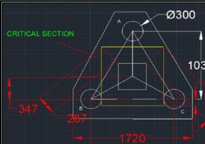
Details about the pile cap of this example
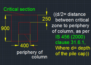
We have assume that the effective depth of pile cap is 500 mm………
Unit Moment at face AB = 0.287×1000= 287 kN-m
Unit Moment at face AC = 0.287×1000= 287 kN-m
Unit Moment at face BC = 0.1×1000= 100 kN-m
Formula used to calculate Area of steel against corresponding moment:
Mu= 0.87 x fy x As t x d (1 – 0.42 x Xu/d)
(AS PER IS:456 (2000) ANNEX G , CLAUSE 38.1………
Mu = Moment
fy = Characteristic strength of steel, here 415
As t = Area of steel
d= Effective depth of pile cap
Xu= Depth of neutral axis
Area of steel required parallel to AB = 1991 mm2
Area of steel required parallel to AC = 1991 mm2
Area of steel required parallel to BC = 693 mm2
We should provide 12 mm rod of 113 mm2
Spacing through AB = (113 x 1000)/1991= 60 mm
Spacing through AC = (113 x 1000)/1991= 60 mm
Spacing through BC = (113 x 1000)/693= 160 mm
OVERALL DEPTH OF THE PILE CAP =(500+(100+12+12+6)X2)= 760 mm