
Do’s & Do not’s For Reinforcement Detailing
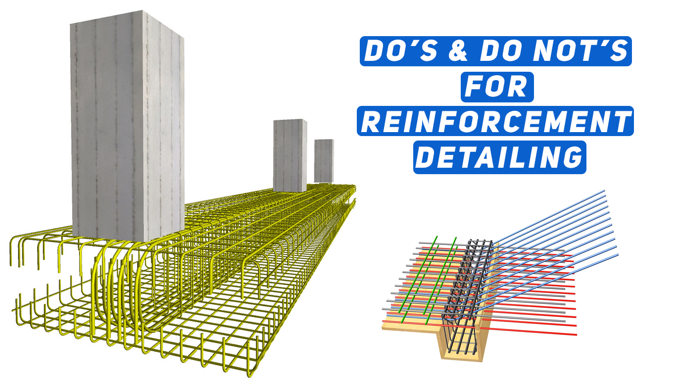
Do’s & Do not’s For Reinforcement Detailing
DO’S-GENERAL Reinforcement Detailing
Prepare drawings properly & accurately if possible label each bar and show its shape for clarity.

1.Cross section of retaining wall which collapsed immediately after placing of soil backfill because ¼” rather than 1-1/4” dia. were used. Error occurred because Correct rebar dia. Was covered by a dimension line.
2.Prepare bar-bending schedule , if necessary.
3. Indicate proper cover-clear cover, nominal cover or effective cover to reinforcement.
4. Decide detailed location of opening/hole and supply adequate details for reinforcements around the openings.
5. Use commonly available size of bars and spirals. For a single structural member the number of different sizes of bars shall be kept minimum.
6. The grade of the steel shall be clearly stated in the drawing.Deformed bars need not have hooks at their ends.
8. Show enlarged details at corners, intersections of walls, beams and column joint and at similar situations.Congestion of bars should be avoided at points where members intersect and make certain that all rein. Can be properly placed.
10. In the case of bundled bars, lapped splice of bundled bars shall be made by splicing one bar at a time; such individual splices within the bundle shall be staggered.
11. Make sure that hooked and bent up bars can be placed and have adequate concrete protection.
12.Indicate all expansion, construction and contraction joints on plans and provide details for such joints.
13.The location of construction joints shall be at the point of minimum shear approximately at mid or near the mid points. It shall be formed vertically and not in a sloped manner.
GENERAL POINTS FOR CALCULATIONS OF REINFORCEMENT
Do’s – Beams & Slabs Reinforcement Detailing:
Where splices are provided in bars, they shall be , as far as possible, away from the sections of maximum stresses and shall be staggered.
Were the depth of beams exceeds 750mm in case of beams without torsion and 450mm with torsion provide face rein. as per IS456-2000.
Deflection in slabs/beams may be reduced by providing compression reinforcement.
Only closed stirrups shall be used for transverse rein. For members subjected to torsion and for members likely to be subjected to reversal of stresses as in Seismic forces.


